В данной статье мы разберем как сделать Тепловизор с помощью датчика AMG8833 и микроконтроллера esp8266. Почему именно ESP8266? Ну во первых она маленькая. Во вторых у нее больше памяти и вычислительной мощности чем в ардуино. А так как тепловизор довольнотаки ресурсо-затратный, то ардуино на мой взгляд хуже справляется с данной задачей.
Прежде чем приступить к материалу, я Вас попрошу, если нравится то, что я делаю и хотите следить за моей деятельностью, то рекомендую подписаться на мой телеграмм канал: https://t.me/ypavla
Там я публикую новости о вышедших видео, статьях и разные устройства для умного дома и не только показываю.
Спасибо за внимание, теперь продолжим.
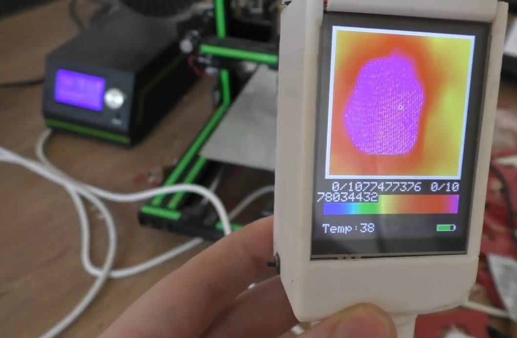
Что же такое тепловизор – устройство для наблюдения за распределением температуры исследуемой поверхности. Распределение температуры отображается на дисплее как цветная картинка, где разным температурам соответствуют разные цвета.
Как уже говорилось температуру будет определять датчик AMG8833. Этот датчик имеет МЭМС матрицу 8×8 и работает по интерфейсу I2C. Угол обзора составляет 60°, а дальность измерения около 7 метров. Максимальная частота формирования кадров составляет 10 кадров/с. Точностью измерений равна ±2.5 °C, а рабочий диапазон температур составляет от 0 до 80 °C.
Датчик AMG8833 можно купить тут : http://ali.pub/2qouqq
В качестве esp8266 я буду использовать плату wemos D1 mini pro. Купить ее можно тут: http://ali.pub/2i2dgk
Дисплей для отображения картинки буду использовать Ili9341, он давольно-таки большой размер у него 2,8 ” дюйма и разрешение 240×320 и на нем можно много чего разглядеть. купить его можно сдесь: http://ali.pub/2qouol
Аккумулятор я взял li-po литий полимерный на 1200mah ссылка на такие аккумы на али: http://ali.pub/2qouyb
Зарядник для lipo аккумуляторов и в формфакторе wemos я покупал тут: http://ali.pub/2q7pvt
Ну и ползунковая кнопка: http://ali.ski/U8fVy
И так, все эти компоненты нужно подключать по вот такой схеме:

Резистор используется на 130kOm
Ну или кому понятнее схема в виде таблички:

Сам скетч выглядит вот таким образом для esp8266:
#ifdef ESP8266

#include <TFT_eSPI.h>

#else

#include <Fonts/FreeMonoBoldOblique12pt7b.h>
#define PIN_CS 15//10                   // chip select for the display
#define PIN_DC 0//9                    // d/c pin for the display

#endif


#include <Adafruit_ILI9341.h>
#include <Adafruit_AMG88xx.h>       // thermal camera lib

#define PIN_INT D0                      // Interrupt from touch for autoscale/scale

// constants for the cute little keypad
#define KEYPAD_TOP 15
#define KEYPAD_LEFT 50
#define BUTTON_W 60
#define BUTTON_H 30
#define BUTTON_SPACING_X 10
#define BUTTON_SPACING_Y 10
#define BUTTON_TEXTSIZE 2

// fire up the display using a very fast driver
// this next line is for my modified library where I pass the screen dimensions in--that way i can use the same lib for my 3.5", 2.8" and other sizes
// ILI9341_t3 Display = ILI9341_t3(PIN_CS, PIN_DC, 240, 320);

// you will need to use this line

#ifdef ESP8266

TFT_eSPI Display = TFT_eSPI();

#else

Adafruit_ILI9341 Display = Adafruit_ILI9341(PIN_CS, PIN_DC);

#endif


// create some colors for the keypad buttons
#define C_BLUE Display.color565(0,0,255)
#define C_RED Display.color565(255,0,0)
#define C_GREEN Display.color565(0,255,0)
#define C_WHITE Display.color565(255,255,255)
#define C_BLACK Display.color565(0,0,0)
#define C_LTGREY Display.color565(200,200,200)
#define C_DKGREY Display.color565(80,80,80)
#define C_GREY Display.color565(127,127,127)

// Added for measure Temp
boolean measure = true;
uint16_t centerTemp;
unsigned long tempTime = millis();
unsigned long batteryTime = 1;

// create some text for the keypad butons
char KeyPadBtnText[12][5] = {"1", "2", "3", "4", "5", "6", "7", "8", "9", "Done", "0", "Clr" };

// define some colors for the keypad buttons
uint16_t KeyPadBtnColor[12] = {C_BLUE, C_BLUE, C_BLUE, C_BLUE, C_BLUE, C_BLUE, C_BLUE, C_BLUE, C_BLUE, C_GREEN, C_BLUE, C_RED };

// start with some initial colors
float MinTemp = 25;
float MaxTemp = 35;

// variables for interpolated colors
byte red, green, blue;

// variables for row/column interpolation
byte i, j, k, row, col, incr;
float intPoint, val, a, b, c, d, ii;
byte aLow, aHigh;

// size of a display "pixel"
byte BoxWidth = 3;
byte BoxHeight = 3;

int x, y;
char buf[20];

// variable to toggle the display grid
int ShowGrid = -1;
int DefaultTemp = -1;

// array for the 8 x 8 measured pixels
float pixels[64];

// array for the interpolated array
float HDTemp[80][80];

// create the keypad buttons
// note the ILI9438_3t library makes use of the Adafruit_GFX library (which makes use of the Adafruit_button library)
Adafruit_GFX_Button KeyPadBtn[12];

// create the camara object
Adafruit_AMG88xx ThermalSensor;

// create the touch screen object
//UTouch  Touch( 2, 3, 4, 5, 6);

void setup() {

  Serial.begin(115200);

  // Set A0 to input for battery measurement
  pinMode(A0, INPUT);

  // start the display and set the background to black
  Display.begin();
  Display.fillScreen(C_BLACK);

  // initialize the touch screen and set location precision
  //Touch.InitTouch();
  //Touch.setPrecision(PREC_EXTREME);

  // create the keypad buttons
  // for (row = 0; row < 4; row++) {
  //   for (col = 0; col < 3; col++) {
  //     KeyPadBtn[col + row * 3].initButton(&Display, BUTTON_H + BUTTON_SPACING_X + KEYPAD_LEFT + col * (BUTTON_W + BUTTON_SPACING_X ),
  //                                         KEYPAD_TOP + 2 * BUTTON_H + row * (BUTTON_H + BUTTON_SPACING_Y),
  //                                         BUTTON_W, BUTTON_H, C_WHITE, KeyPadBtnColor[col + row * 3], C_WHITE,
  //                                         KeyPadBtnText[col + row * 3], BUTTON_TEXTSIZE);
  //   }
  // }

  // set display rotation (you may need to change to 0 depending on your display
  Display.setRotation(0);

  // show a cute splash screen (paint text twice to show a little shadow

  // Display.setFont(&FreeMonoBoldOblique12pt7b);
  // Display.setFont(DroidSans_40);
  Display.setTextSize(2);
  Display.setCursor(62, 61);
  Display.setTextColor(C_WHITE, C_BLACK);
  Display.print("Thermal");

  //Display.setFont(DroidSans_40);
  Display.setCursor(60, 60);
  Display.setTextColor(C_BLUE);
  Display.print("Thermal");

  //Display.setFont(Arial_48_Bold_Italic);
  Display.setCursor(92, 101);
  Display.setTextColor(C_WHITE, C_BLACK);
  Display.print("Camera");

  //Display.setFont(Arial_48_Bold_Italic);
  Display.setCursor(90, 100);
  Display.setTextColor(C_RED);
  Display.print("Camera");


  // let sensor boot up
  bool status = ThermalSensor.begin();
  delay(100);

  // check status and display results
  if (!status) {
    while (1) {
      //Display.setFont(DroidSans_20);
      Display.setCursor(20, 180);
      Display.setTextColor(C_RED, C_BLACK);
      Display.print("Sensor: FAIL");
      delay(500);
      //Display.setFont(DroidSans_20);
      Display.setCursor(20, 180);
      Display.setTextColor(C_BLACK, C_BLACK);
      Display.print("Sensor: FAIL");
      delay(500);
    }
  }
  else {
    //Display.setFont(DroidSans_20);
    Display.setCursor(20, 180);
    Display.setTextColor(C_GREEN, C_BLACK);
    Display.print("Sensor: FOUND");
  }

  // read the camera for initial testing
  ThermalSensor.readPixels(pixels);

  // check status and display results
  if (pixels[0] < 0) { while (1) { //Display.setFont(DroidSans_20); Display.setCursor(20, 210); Display.setTextColor(C_RED, C_BLACK); Display.print("Readings: FAIL"); delay(500); //Display.setFont(DroidSans_20); Display.setCursor(20, 210); Display.setTextColor(C_BLACK, C_BLACK); Display.print("Readings: FAIL"); delay(500); } } else { // Display.setFont(DroidSans_20); Display.setCursor(20, 210); Display.setTextColor(C_GREEN, C_BLACK); Display.print("Readings: OK"); delay(2000); } // set display rotation and clear the fonts..the rotation of this display is a bit weird //Display.setFontAdafruit(); Display.fillScreen(C_BLACK); // Display.setFont(); // get the cutoff points for the color interpolation routines // note this function called when the temp scale is changed Getabcd(); // draw a cute legend with the scale that matches the sensors max and min DrawLegend(); // draw a large white border for the temperature area Display.fillRect(10, 10, 220, 220, C_WHITE); } void loop() { // if someone touched the screen do something with it // if (Touch.dataAvailable()) { // ProcessTouch(); // } if (digitalRead(PIN_INT) == false) { SetTempScale(); if (millis() - tempTime > 2000) {
      measure = !measure;
      tempTime = millis();
      Display.fillRect (0, 300, 100, 16, ILI9341_BLACK);
    }
  }
  else {
    tempTime = millis();
  }

  // read the sensor
  ThermalSensor.readPixels(pixels);

  // now that we have an 8 x 8 sensor array
  // interpolate to get a bigger screen
  InterpolateRows();

  // now that we have row data with 70 columns
  // interpolate each of the 70 columns
  // forget Arduino..no where near fast enough..Teensy at > 72 mhz is the starting point
  InterpolateCols();

  // display the 70 x 70 array
  DisplayGradient();

  // Update battery everx 30s
  if (batteryTime < millis()) {
    drawBattery();
    batteryTime = millis() + 30000;
  }
}


// interplation function to create 70 columns for 8 rows
void InterpolateRows() {

  // interpolate the 8 rows (interpolate the 70 column points between the 8 sensor pixels first)
  for (row = 0; row < 8; row ++) {
    for (col = 0; col < 70; col ++) {
      // get the first array point, then the next
      // also need to bump by 8 for the subsequent rows
      aLow =  col / 10 + (row * 8);
      aHigh = (col / 10) + 1 + (row * 8);
      // get the amount to interpolate for each of the 10 columns
      // here were doing simple linear interpolation mainly to keep performace high and
      // display is 5-6-5 color palet so fancy interpolation will get lost in low color depth
      intPoint =   (( pixels[aHigh] - pixels[aLow] ) / 10.0 );
      // determine how much to bump each column (basically 0-9)
      incr = col % 10;
      // find the interpolated value
      val = (intPoint * incr ) +  pixels[aLow];
      // store in the 70 x 70 array
      // since display is pointing away, reverse row to transpose row data
      HDTemp[ (7 - row) * 10][col] = val;

    }
  }
}

// interplation function to interpolate 70 columns from the interpolated rows
void InterpolateCols() {

  // then interpolate the 70 rows between the 8 sensor points
  for (col = 0; col < 70; col ++) {
    for (row = 0; row < 70; row ++) {
      // get the first array point, then the next
      // also need to bump by 8 for the subsequent cols
      aLow =  (row / 10 ) * 10;
      aHigh = aLow + 10;
      // get the amount to interpolate for each of the 10 columns
      // here were doing simple linear interpolation mainly to keep performace high and
      // display is 5-6-5 color palet so fancy interpolation will get lost in low color depth
      intPoint =   (( HDTemp[aHigh][col] - HDTemp[aLow][col] ) / 10.0 );
      // determine how much to bump each column (basically 0-9)
      incr = row % 10;
      // find the interpolated value
      val = (intPoint * incr ) +  HDTemp[aLow][col];
      // store in the 70 x 70 array
      HDTemp[ row ][col] = val;
    }
  }
}

// function to display the results
void DisplayGradient() {

  // rip through 70 rows
  for (row = 0; row < 70; row ++) {

    // fast way to draw a non-flicker grid--just make every 10 pixels 2x2 as opposed to 3x3
    // drawing lines after the grid will just flicker too much
    if (ShowGrid < 0) {
      BoxWidth = 3;
    }
    else {
      if ((row % 10 == 9) ) {
        BoxWidth = 2;
      }
      else {
        BoxWidth = 3;
      }
    }
    // then rip through each 70 cols
    for (col = 0; col < 70; col++) {

      // fast way to draw a non-flicker grid--just make every 10 pixels 2x2 as opposed to 3x3
      if (ShowGrid < 0) { BoxHeight = 3; } else { if ( (col % 10 == 9)) { BoxHeight = 2; } else { BoxHeight = 3; } } // finally we can draw each the 70 x 70 points, note the call to get interpolated color Display.fillRect((row * 3) + 15, (col * 3) + 15, BoxWidth, BoxHeight, GetColor(HDTemp[row][col])); if (measure == true && row == 36 && col == 36) { drawMeasurement(); //Draw after center pixels to reduce flickering } } } } // my fast yet effective color interpolation routine uint16_t GetColor(float val) { /* pass in value and figure out R G B several published ways to do this I basically graphed R G B and developed simple linear equations again a 5-6-5 color display will not need accurate temp to R G B color calculation equations based on http://web-tech.ga-usa.com/2012/05/creating-a-custom-hot-to-cold-temperature-color-gradient-for-use-with-rrdtool/index.html */ red = constrain(255.0 / (c - b) * val - ((b * 255.0) / (c - b)), 0, 255); if ((val > MinTemp) & (val < a)) { green = constrain(255.0 / (a - MinTemp) * val - (255.0 * MinTemp) / (a - MinTemp), 0, 255); } else if ((val >= a) & (val <= c)) { green = 255; } else if (val > c) {
    green = constrain(255.0 / (c - d) * val - (d * 255.0) / (c - d), 0, 255);
  }
  else if ((val > d) | (val < a)) {
    green = 0;
  }

  if (val <= b) { blue = constrain(255.0 / (a - b) * val - (255.0 * b) / (a - b), 0, 255); } else if ((val > b) & (val <= d)) { blue = 0; } else if (val > d) {
    blue = constrain(240.0 / (MaxTemp - d) * val - (d * 240.0) / (MaxTemp - d), 0, 240);
  }

  // use the displays color mapping function to get 5-6-5 color palet (R=5 bits, G=6 bits, B-5 bits)
  return Display.color565(red, green, blue);

}

// function to automatically set the max / min scale based on adding an offset to the average temp from the 8 x 8 array
// you could also try setting max and min based on the actual max min
void SetTempScale() {

  if (false ) { //DefaultTemp < 0) {
    MinTemp = 25;
    MaxTemp = 35;
    Getabcd();
    DrawLegend();
  }
  else {
    MinTemp = 255;
    MaxTemp = 0;

    for (i = 0; i < 64; i++) { MinTemp = min(MinTemp, pixels[i]); //MaxTemp = max(MaxTemp, pixels[i]); if (pixels[i] > MaxTemp) { MaxTemp = pixels[i];}

    }

    MaxTemp = MaxTemp + 5.0;
    MinTemp = MinTemp + 3.0;
    Getabcd();
    DrawLegend();
  }

}

// function to get the cutoff points in the temp vs RGB graph
void Getabcd() {

  a = MinTemp + (MaxTemp - MinTemp) * 0.2121;
  b = MinTemp + (MaxTemp - MinTemp) * 0.3182;
  c = MinTemp + (MaxTemp - MinTemp) * 0.4242;
  d = MinTemp + (MaxTemp - MinTemp) * 0.8182;

}

// function to handle screen touches
//void ProcessTouch() {
//
//  Touch.read();
//
//  x = Touch.getX();
//  y = Touch.getY();

// yea i know better to have buttons
//  if (x > 200) {
//    if (y < 80) { // KeyPad(MaxTemp); // } // else if (y > 160) {
//      KeyPad(MinTemp);
//    }
//    else {
//      DefaultTemp = DefaultTemp * -1;
//      SetTempScale();
//    }
//  }

//  else if (x <= 200) { // toggle grid // ShowGrid = ShowGrid * -1; // if (ShowGrid > 0) {
//      Display.fillRect(15, 15, 210, 210, C_BLACK);
//    }
//  }
//}

// function to draw a cute little legend
void DrawLegend() {

  // my cute little color legend with max and min text
  j = 0;

  float inc = (MaxTemp - MinTemp ) / 220.0;

  for (ii = MinTemp; ii < MaxTemp; ii += inc) { // Display.drawFastHLine(10, 255 - j++, 30, GetColor(ii)); Display.drawFastVLine(10 + j++, 255, 30, GetColor(ii)); } Display.setTextSize(2); Display.setCursor(10, 235); Display.setTextColor(C_WHITE, C_BLACK); sprintf(buf, "%2d/%2d", MinTemp, (int) (MinTemp * 1.8) + 32); // Display.fillRect(233, 15, 94, 22, C_BLACK); // Display.setFont(Arial_14); Display.print(buf); Display.setTextSize(2); // Display.setFont(Arial_24_Bold); Display.setCursor(170, 235); Display.setTextColor(C_WHITE, C_BLACK); sprintf(buf, "%2d/%2d", MaxTemp, (int) (MaxTemp * 1.8) + 32); // Display.fillRect(233, 215, 94, 55, C_BLACK); // Display.setFont(Arial_14); Display.print(buf); } // Draw a circle + measured value void drawMeasurement() { // Mark center measurement Display.drawCircle(120, 120, 3, ILI9341_WHITE); // Measure and print center temperature centerTemp = pixels[27]; Display.setCursor(10, 300); Display.setTextColor(ILI9341_WHITE, ILI9341_BLACK); Display.setTextSize(2); sprintf(buf, "%s:%2d", "Temp", centerTemp); Display.print(buf); } int measureBattery() { uint16_t adcValue = analogRead(A0); int volt = adcValue / 102.3 * 4.5;// Using 130kOhm resistor return volt; } // Draw battery symbol void drawBattery() { int volt = measureBattery() - 32; // range from 3.2V - 4.2V volt = max (volt, 1); volt = min (volt, 10); // draw battery Display.drawRect(198, 304, 30, 10, C_WHITE); Display.fillRect(227, 306, 3, 6, C_WHITE); Display.fillRect(199, 305, 28, 8, C_BLACK); if (volt > 3)Display.fillRect(199, 305, volt * 3 - 2 , 8, C_GREEN);
  else Display.fillRect(199, 305, volt * 3 - 2, 8, C_RED);


}
Скачать скетч: https://yadi.sk/d/k2E7LFmA9aigXw
Для увеличения частоты кадров Wemos нужно выбрать не на 80Mhz а на 160Mhz.
Необходимые библиотеки (В Arduino IDE в управлении библиотеками):
- Библиотека Adafruit AMG88xx
- Adafruit ILI9341
- Библиотека Adafruit GFX
- для ESP8266 (папки, заканчивающиеся на TFT_eSPI), TFT_eSPI импорт ZIP из ( https://github.com/Bodmer/TFT_eSPI )
Для версий ESP8266 в папке с библиотекой TFT_eSPI раскомментируйте следующие строки в User_Setup.h:
define ILI9341_DRIVER
Далее
#define TFT_CS PIN_D8 // Chip select control pin D8
#define TFT_DC PIN_D3 // Data Command control pin
//#define TFT_RST PIN_D4 // Reset pin (could connect to NodeMCU RST, see next line)
#define TFT_RST -1 // Set TFT_RST to -1 if the display RESET is connected to NodeMCU RST or 3.3V
Все больше редактировать в User_setup.h ничего ненужно.
Корпус тепловизора для 3d печати: https://yadi.sk/d/o20BYmyxi4_fKw
Печаталось все на принтере Anet e10: http://ali.pub/2qoxl7
Визуальная работа тепловизора в видео: